Captando energia eólica
15 outubro, 2007 at 11:11 am 2 comentários
Navegando pelos projetos diy, achei um muito interessante. Produzir energia sustentável através do vento, constuindo um moinho. Abaixo segue um passo-a-passo de como fazer seu próprio captador de energia eólica.
Foi retirado do site: http://www.thebackshed.com/
This new windmill for the F&P motor was designed to be easy to build, and needs no special laser cut parts. You should be able to put it together with some basic metal working tools and a welder.
| Check that both ends of the 65mm box section are square, dont trust the supplier to cut them square for you. | 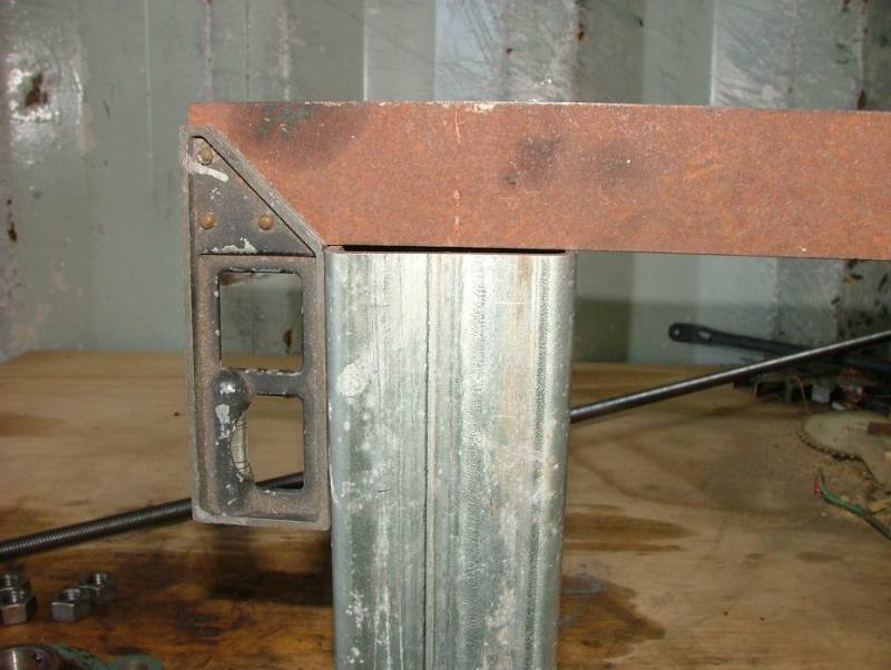 |
| Cut a piece of steel plate 4mm to 8mm thick as shown. The 5mm holes are to be threaded later. (Tip – If you get this plate laser cut, cut the holes smaller than 5mm, then drill to 5mm. Laser cutting hardens the cut edge and this will make taping harder. ) | 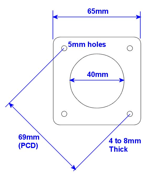 |
| Tac and weld the rear plate onto the 65mm box section, check that it is square. | 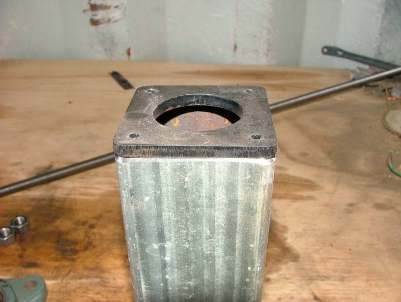 |
| Cut the 12mm all-thread into 4 lengths of 80mm long. Clean up one end so the nuts go on easily. | 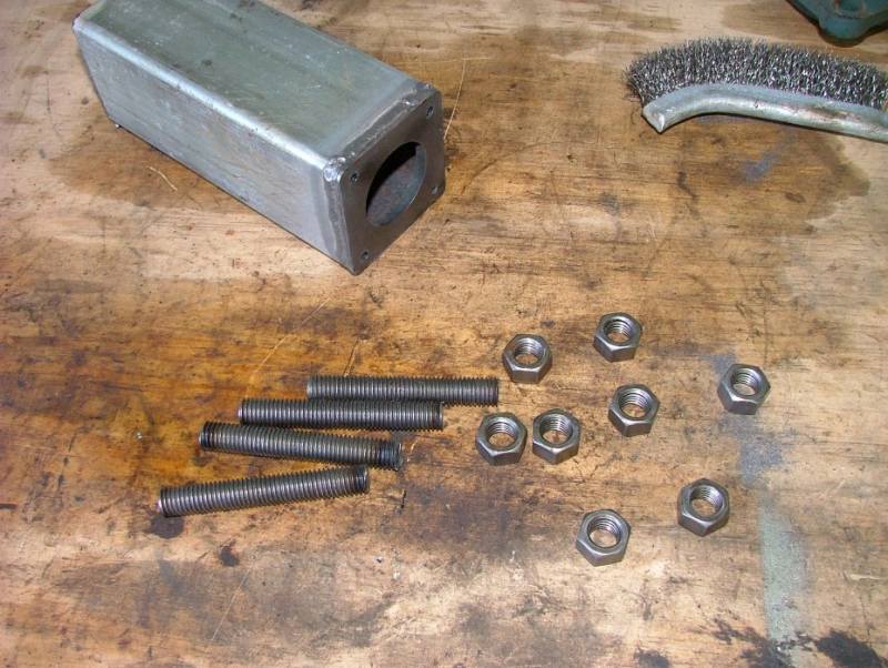 |
| Bolt the all-thread to the 56205 bearing as shown, using a nut on both sides. | 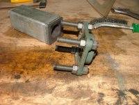 |
| Sit the bearing on the other end of the 65mm box section. The all-thread will line up with the box corners. Tac each thread in a couple of places to the box section. | 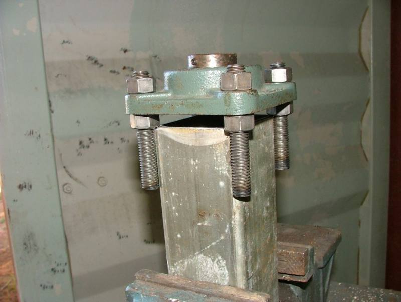 |
| Remove the bearing, and fully weld the all-thread’s to the box section. | 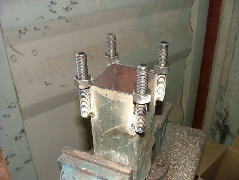 |
| Drill/file two 16mm holes into the end of the 40mm box section. The holes are offset from each other by about 10mm. The top hole is closer to the end of the 40mm box. Use the diagram as a guide. | 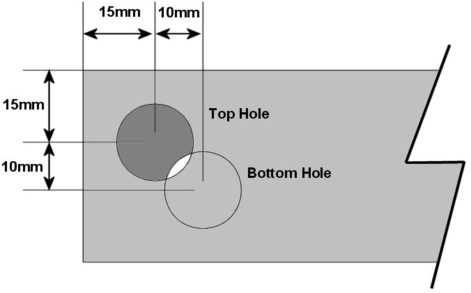 |
| Make sure the 16mm rod slides through. These offset holes will hold the rod at the angle needed for our furling tail. Angle is not critical, we adjust furling later with tail length and weight. | 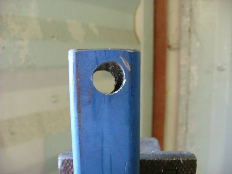 |
| Tac and weld the 40mm box onto the 65mm box, about 10mm in from then end we bolt the stator to. Make sure the 16mm hole closest to the end of the 40mm box is facing up and back. This photo was taken from the under side of the windmill. | 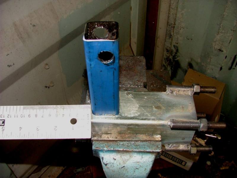 |
| Sit the 50mm id pipe on the windmill as shown. The pipe sits in the middle of it length here, but this is not critical. Make sure its square, and fully weld. Make sure you weld down both sides of the pipe, its a tight angle to weld in but important. This is our yaw bearing. | 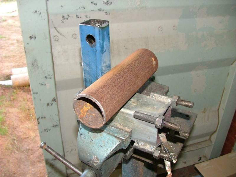 |
| Cut 4 triangle pieces of scrap steel, about 25 * 25mm. |  |
| And weld these onto the windmill as shown. These give more strength. |  |
| Once all the welding is done, tap out the 6mm holes to suit the 6mm stator retaining bolts. Its best to do this after welding as any welding splatter will quickly stuff a thread. |  |
| With the windmill secured in its normal upright position, slide in the 220mm long 16mm rod. | 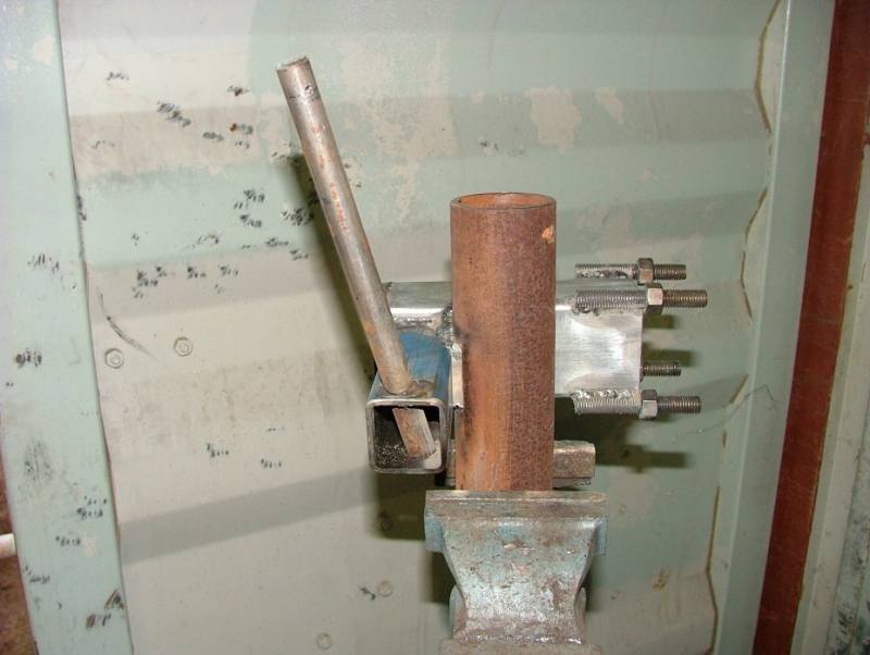 |
| Looking from the front, the rod will point to the left and back from the windmill. Weld in place, both top and bottom where it passes through the 40mm box section. |  |
| Cut a 60mm and 100mm lengths of 22mm od 16mm id tube. Then cut one end of each as shown. Click on the diagram to enlarge. | 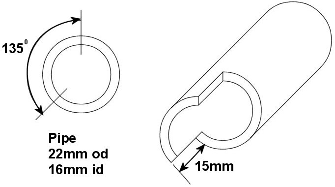 |
| The cut tube, note this photo was taken during development, so the lengths appear wrong. Slide the short tube over the rod till it hits bottom, and weld around the base. The slotted end will be pointing up. It dosn’t matter which direction the slot is facing. | 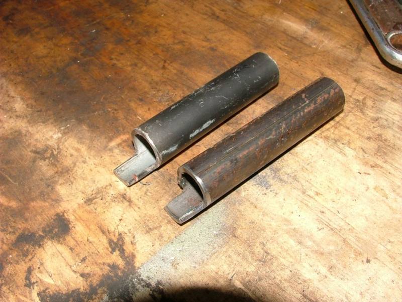 |
| Make a washer from some 6mm ( or thicker ) steel. id is 30mm, od 52mm. Weld this to the top of the 50mm id tube ( yaw bearing ). This washer stops the windmill sliding down the mast. You may see I’ve also welded a small strip of scrap steel with a elongated hole in it to the top of the windmill ( its upside down in this photo ). This will be used later a a mounting point for the rectifier. Any old bit of steel with a couple of holes in it will do. |  |
| Slide the 100mm length of 22mm tube onto the tail hinge, so that the two tangs we made earlier engage. This is our tail hinge. Looking from the top, rotate the hinge tube counter clockwise till it stops. You should have about 90 degrees of rotation. Grab you remaining length of 22mm tube ( the tail arm ) and tac it to the hinge so that the tail arm is level AND pointing straight out from the back of the windmill. |  |
| Once you have it tacked at the right angle, fully weld. Add a small brace to give more support. You can see here I used an old bolt as the brace. | 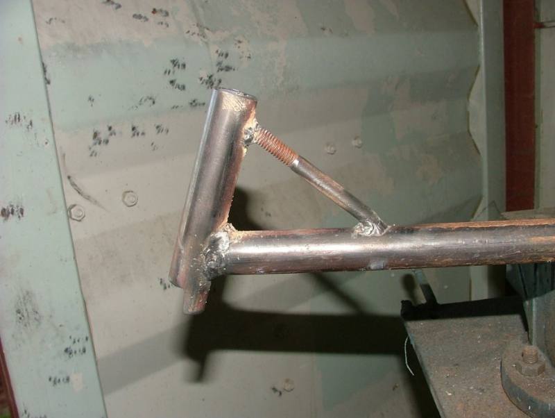 |
| When the windmill is held level in a vice, the tail arm should sit directly out from the back of the windmill. Rotate the arm and it will swing up and over the windmill. You’ll see here the stator and hub are fitted, we’ll get to this soon. | 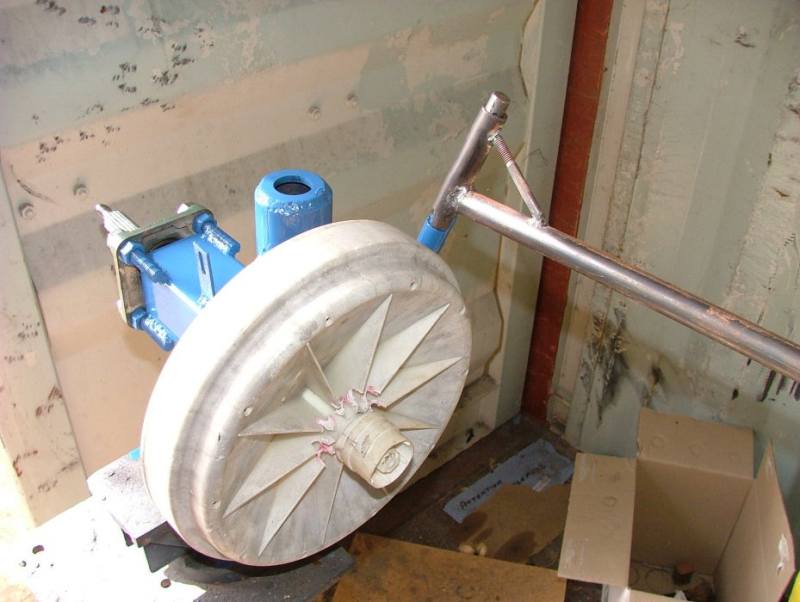 |
| This is the furled position.With the tail at it normal rest position, position your tail fin so it is vertical and mark/drill the mounting holes for the tail fin. | 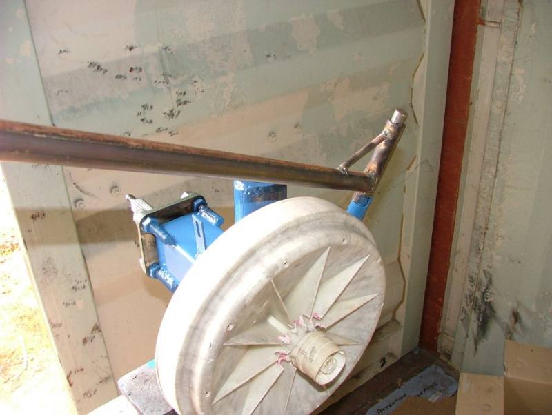 |
| Cable retainer.There are three designs I’ll show here. The first is the simplest, but no good if you have a tilt tower like mine. | 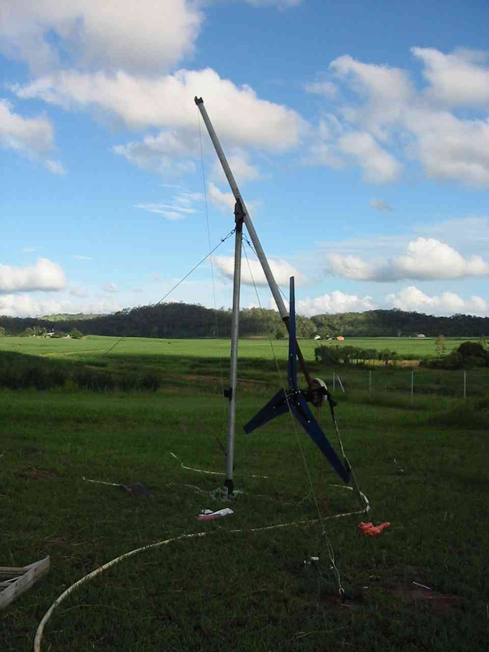 |
| This design is easy to make, as shown in the diagram. Remember you can click on these diagrams and pictures for a full size picture.The windmill slides over the top of the tower, and relies on gravity to keep it there. The drop wire is secured to the outer tube ( part of the windmill ) with a couple of cable ties, or better still, large hose clamps. It then hangs down the middle of the tower. | 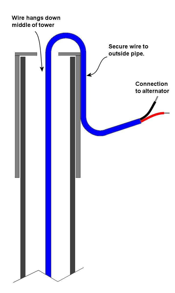 |
| A better design uses an small extension on the tower with a bolt to stop the windmill sliding off the top of the tower. As my windmill tower is a tilt tower, when I tilt the tower over the windmill can slide off and damage the blades. So this is the way I went.The problem is you must guide the power wire down the middle of the extension, or it will get caught on the retaining bolt or bind against the extension inner wall as the windmill yaws.
So you could use a short length of copper tube bent in a U shape, and feed the power wide through this tube. Make sure you secure the copper tube to the windmill’s outer tube with hose clamps or U bolts. See the diagram. |
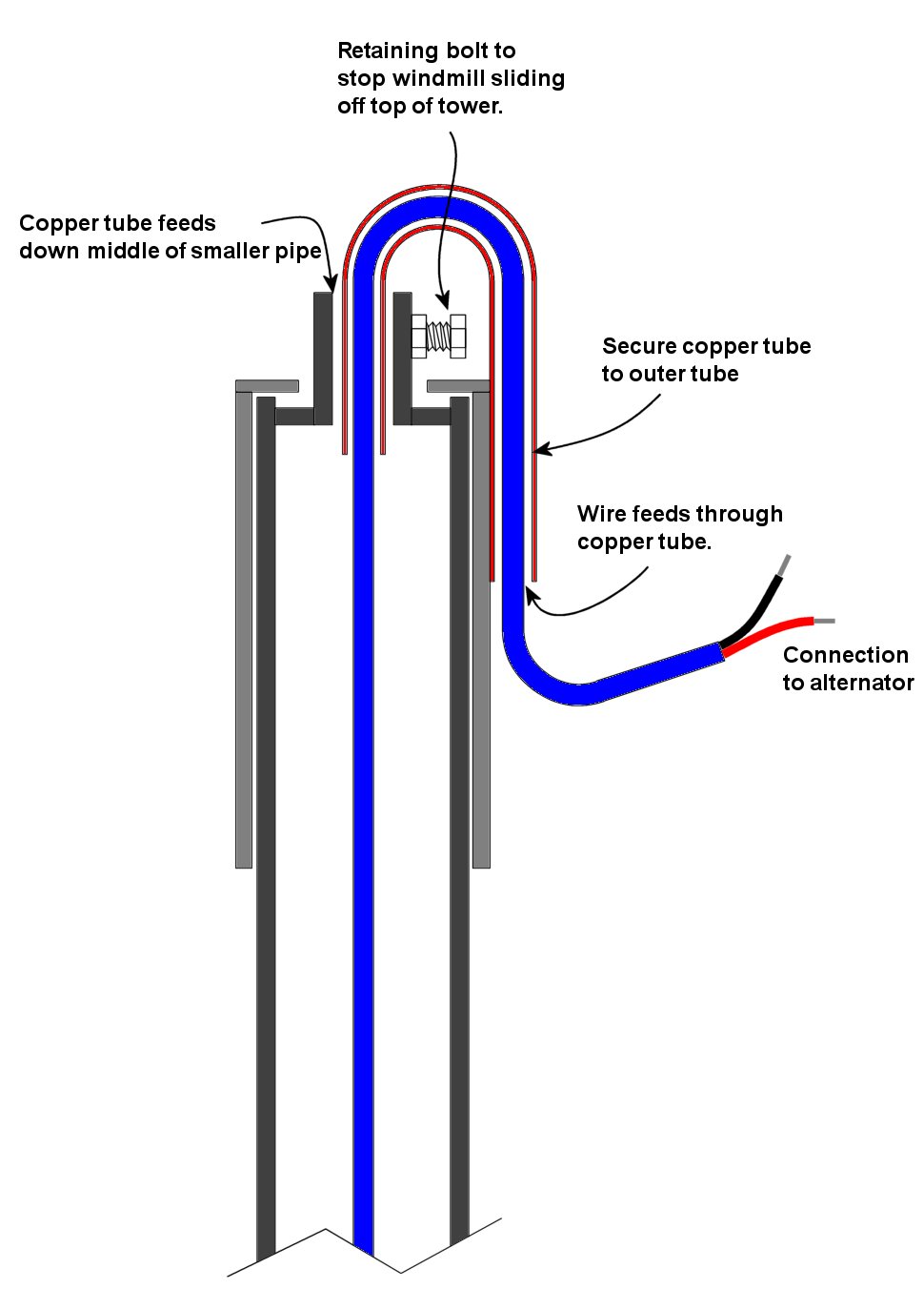 |
| Or you could do as I’ve done and welded a U shaped length of 25mm wide flat bar. |  |
| I drilled some holes in the flat bar to take cable ties, you see how I attached the cable in the next couple of pages. | 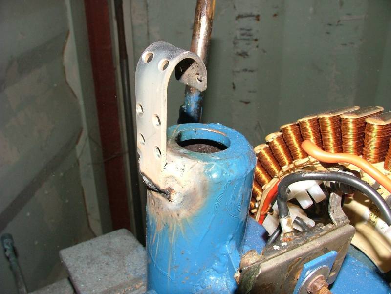 |
| Next clean up your welds and paint the windmill with a durable exterior paint. I used blue Rust Guard. | 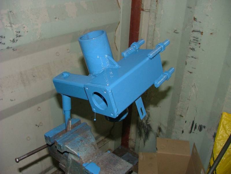 |
| Fit the front bearing, use a little locktight or split washers to secure the nuts.. |  |
| Slide in the F&P shaft from the back. | 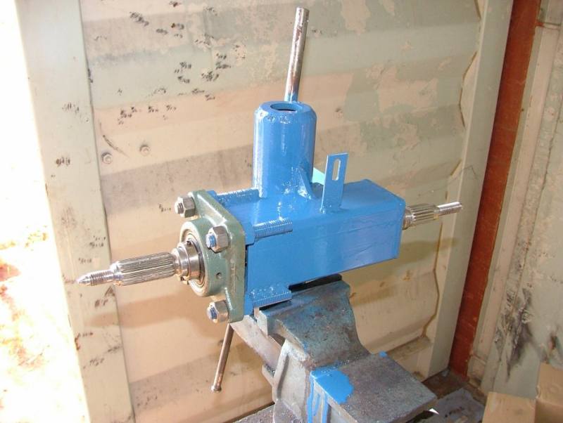 |
| Next you will need the rear bearing support. You can make this from anything durable, ie aluminium, steel, even a bit of plastic or hardwood. It needs to be 7 to 8mm thick. The 47mm hole in the middle needs to be spot on, as this holds the 6005 bearing. | 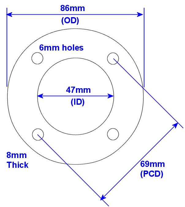 |
| I cheated and used a old bearing plate from an earlier lasercut windmill. Press in the 6005 bearing, should be a tight fit. The bearing sits flush on one side, and pokes out 4mm on the other ( the side that fits into the stator ) | 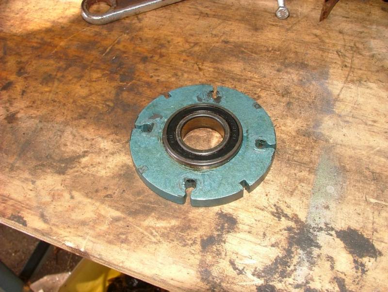 |
| Slide the bearing plate over the F&P shaft and fit the retaining nut. Use a little locktight on the bearing where it fits on the shaft, and thread. |  |
| Next we mount the stator. Dont forget to use the metal plates that come with the stator. | 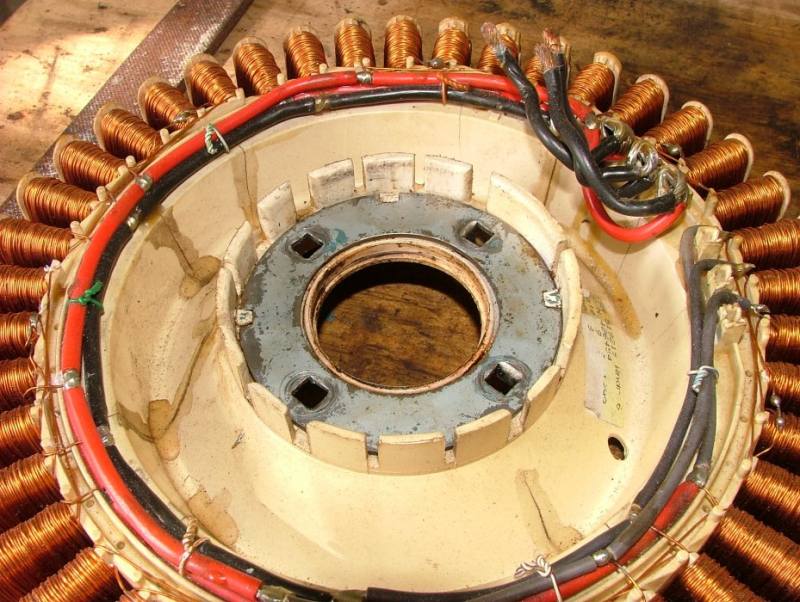 |
| Bolt the stator to the windmill with the four 6mm bolts. Again use some locktight or spit washers. |  |
| Looking from the front, make sure the wires from the stator are not in the way of the tail brace. | 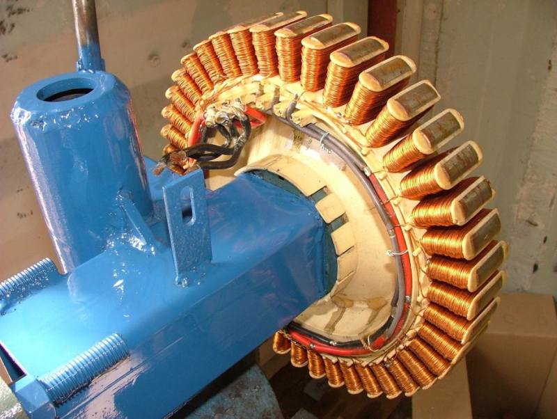 |
| My mast diameter is 48mm od 40mm id. Cut a washer 40mm od and 22mm id. Cut a 40mm length of the 22mm od pipe, then drill a 9 mm hole through one end. Weld these together. | 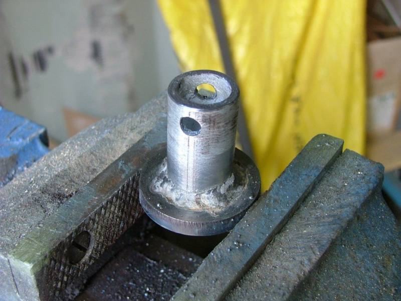 |
| Then weld this into the end of the mast. I pushed mine down into the mast about 5 mm before welding | 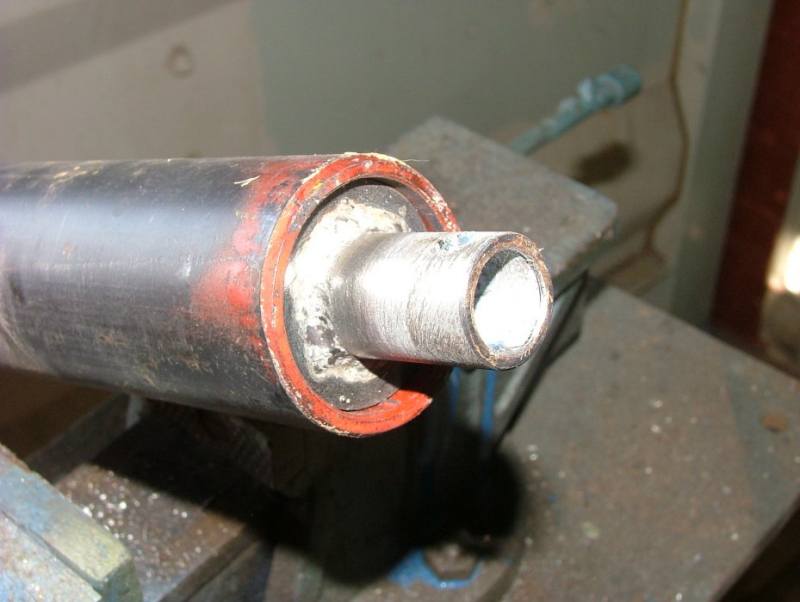 |
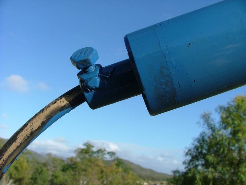
| Weld a 8mm nut over the hole drilled in the side of the 22mm tube. This photo was take after the mast was painted. Check that the windmill can slide over the nut. Once a bolt is fitted, the windmill can’t slide off. |
|
| Slide the windmill over the tower and screw in the retaining bolt to stop it sliding off. Dont forget to apply some grease to the mast first. You can see the power drop wire poking through the 22mm tube on the end of the mast. Tip – feed your power cable through your mast before you lift it off the ground. | 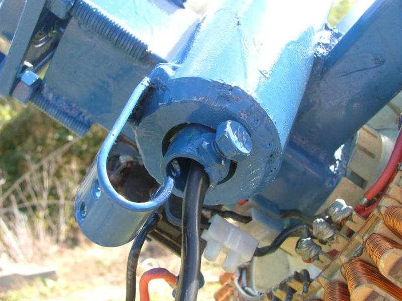 |
| Secure the drop cable to the U bar with cable ties. This U bar will take the weight of the drop wire and feed it down the middle of the 22mm tube. The cable should not rub against the tube as the windmill yaws. | 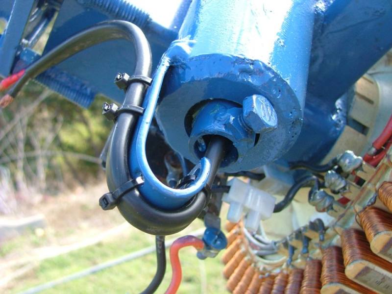 |
| Then connect the drop wire to the rectifier. |  |
| This is the propeller I used for my old F&P windmill. The blades were made by Dennis Latham in Adelaide, and I recently reshaped the blade root and gave them a new coat of paint. There are other web sites about making your own timber blades, so I wont go into it here. Check out the websites on my Links page. For more infomation on blades, click here. | 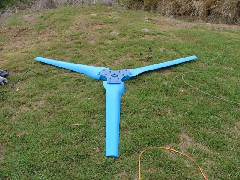 |
| These hub plates are lasercut, and have a internal spline that fits the F&P shaft. You might notice the balancing plate on one side. This photo is looking at the back of the propeller. | 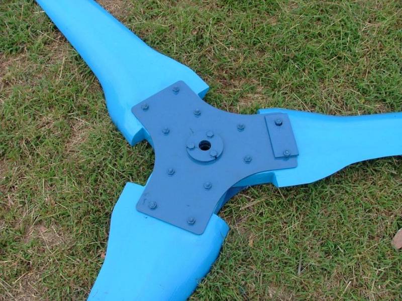 |
| But for your windmill I would weld a piece of 8mm plate cut like a large washer ( 25mm id, 90mm od) onto the F&P shaft ( push the plate up against the bearing and check its square before welding ), then bolt a larger 300mm diameter 3mm thick disk of steel or aluminium to hold the blades. Use two 3mm plates, one in front and one behind the blades. | 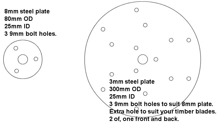 |
| The propeller bolted to the windmill. Dont forget to screw on the F&P Hub. I’ve painted my hub, as they are made of a plastic that will degrade in full sunlight. | 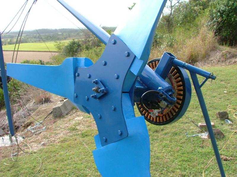 |
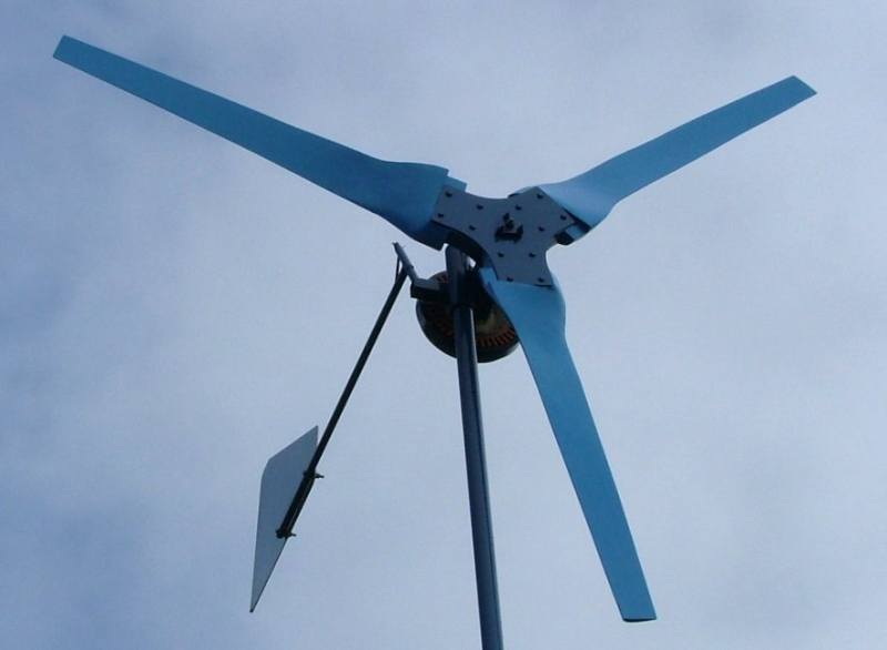
| And up in the air.I’ve skipped a few details, like how to connect the rectifier, modify the stator. Have a look at the old laser cut design ( in the Projects/Assemble section ) for these details. | 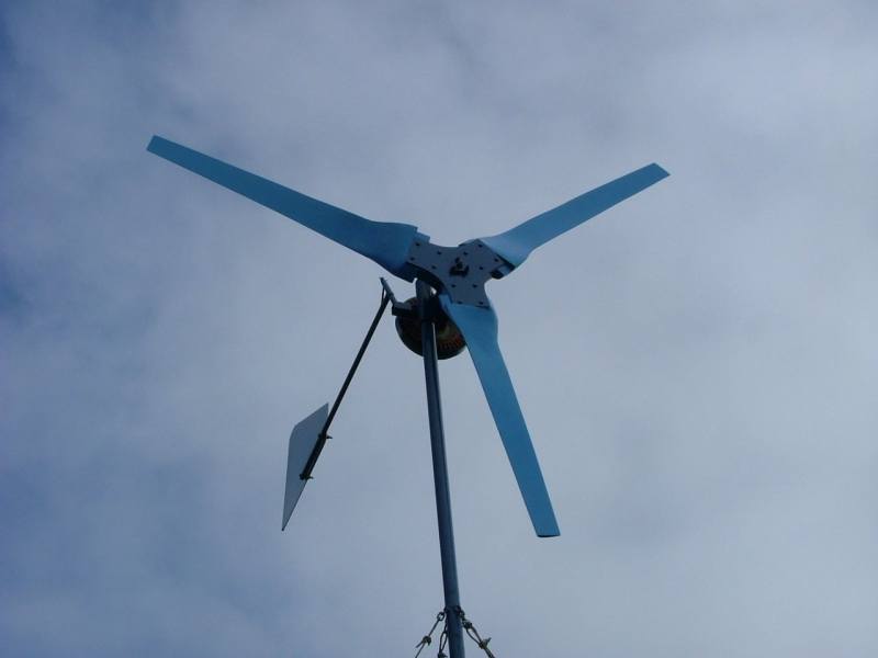 |
Entry filed under: energia. Tags: energia eólica, vento.
2 Comentários Add your own
Deixe um comentário
Trackback this post | Subscribe to the comments via RSS Feed

1. renato coutinho | 17 janeiro, 2010 às 4:23 pm
vc ñ tem prjetos mais baratos ?
muito istrutivo o seu projeto .
2. aerogenpatagon | 12 setembro, 2010 às 10:47 pm
Muy buen generador, pero faltan algunos datos, potencia, velocidad máxima, costos. Interesante de todos modos.
Saludos
Visiten también, http://aerogenpatagon.wordpress.com/ , energía eólica en argentina.